Miniature Train
Miniature toy train
The Miniature Train project is a project that we completed where we used Inventor (CAD program) to model a miniature toy train. We modeled the individual parts then assembled it to form the train. We also dimensioned each of the parts.
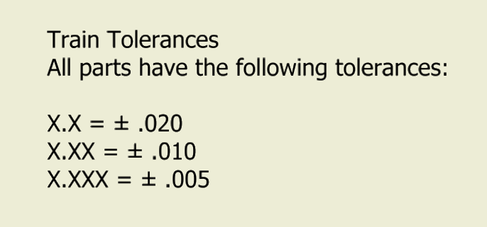
Dimensioned Drawings
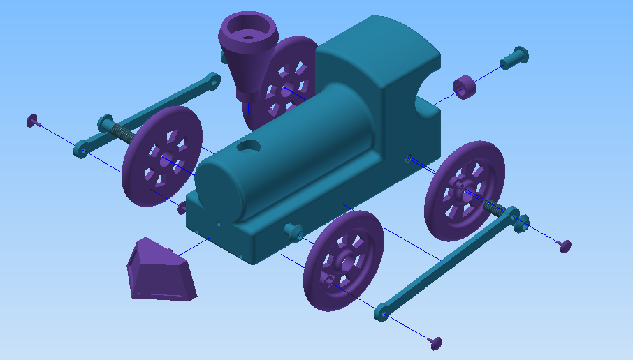
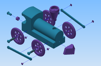
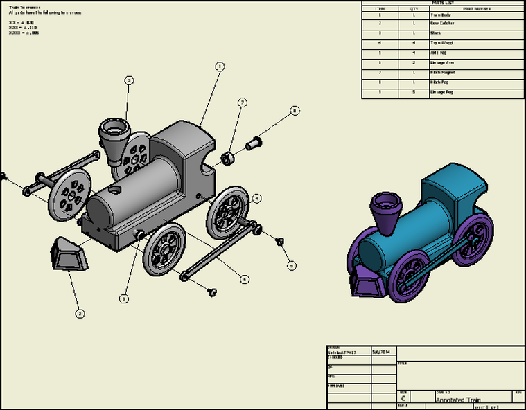
Isometric exploded view
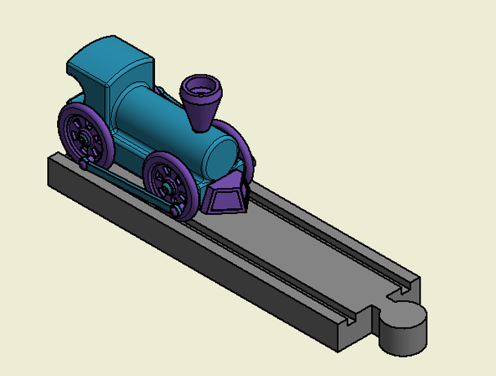
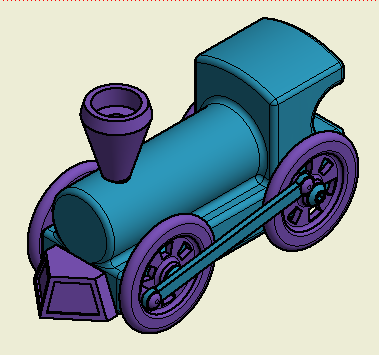
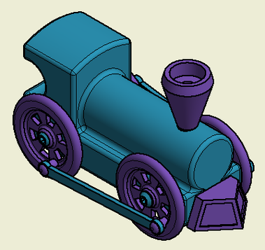
Isometric assembled view |
|
|
|
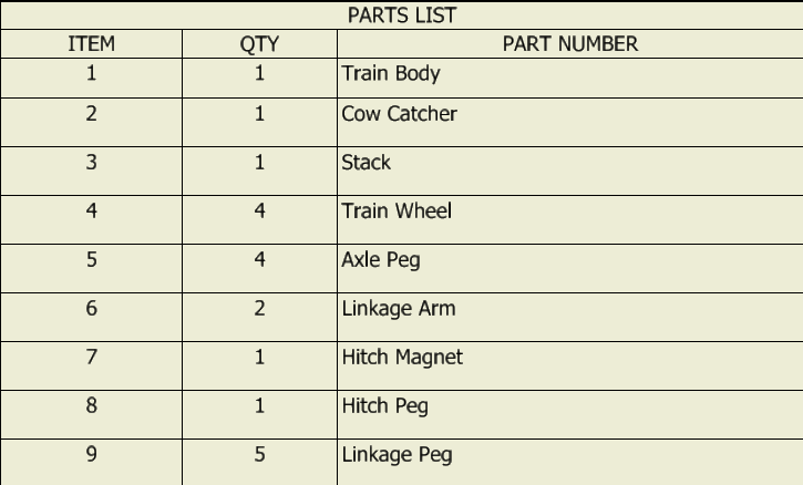
Parts list / annotated balloons
|
|
Conclusion
While completing the Miniature Train Project I faced some
challenges with dimensioning and modeling parts. When I was modeling the
individual parts, I would start a part and then realize I was doing it the
wrong way so I would have to start over and redo the part in a different way. Another
problem I had was while I was dimensioning, I would forget some dimensions and
over dimension other parts. Another dimensioning problem I had was while
dimensioning my stack, I wasn’t able to make the dimension for the counter bore
hole correctly. Some of the skills I learned were making sectional views,
broken views and auxiliary views in Inventor. I also learned how to make
different tolerances in Inventor.
- Section views are used to show the inside of an
object, like holes, which can’t be seen from the outside of an object.
- An auxiliary view is used to show the slope on a
part in Inventor. The straight front view of an object could be misleading to
how the part actually looks.
- A broken view is used when a part is too long to
fit on the .idw sheet. An example is the Straight Track, which is 12 inces
long. To fit that on an .idw drawing sheet you would have to use the broken
view to both view and dimension the whole part.
- Symbols are used to identify holes because symbols
take up less room on the .idw sheet and they are easier to read.
- Tolerances are used because it is nearly
impossible to build a perfect part so the tolerances add a little bit of leeway
for a part to fit where it needs to be and to function properly.
