Toll Booth
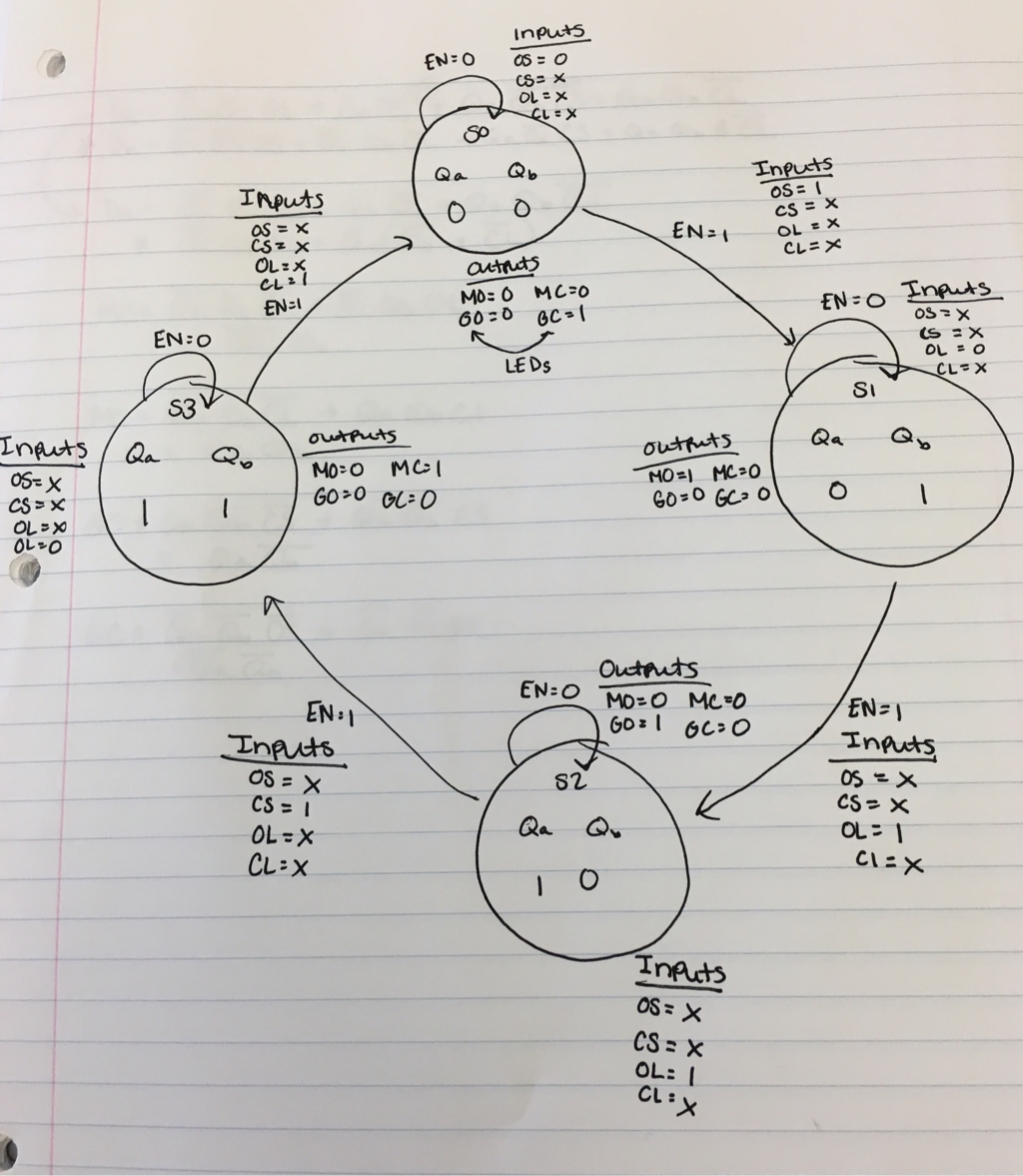
State Graph
|
Inputs
Open switch (OS) - The open switch is a switch or button that when pressed, causes the arm of the toll booth to move from the closed position to the open position. Close switch (CS) - The close switch is a switch or button that when pressed, causes the arm of the toll booth to move from the open position to the closed position. Open limit (OL) - The open limit is a limit switch that is attached to the structure of the toll booth. When the arm of the toll booth raises from the closed position to the open and hits the limit switch, the motor stops so that the arm remains in the open position. Close limit (CL) - The close limit is a limit switch that is attached to the structure of the toll booth. When the arm of the toll booth lowers from the open position to the closed position, and the limit switch is hit, the motor stops so that the arm of the toll booth remains in the closed position. |
Outputs
Motor open (MO) - When this output is a 1, the motor is on and running so that the arm of the toll booth is raising to the open position. Motor close (MC) - When this output is a 1, the motor is on and running so that the arm of the toll booth is lowering to the closed position. Gate open (GO) - The GO output is connected to an LED so that when the arm of the toll booth is fully raised, and touching the OL the LED is on. Gate close (GC) - The GC output is connected to an LED so that when the arm of the toll booth is fully closed, and touching the CL the LED is on. States
There are two state variables in each state Qa (Qa = Da) and Qb Qb=Db) In state 0 (S0), the arm is in the closed position and the motor is not on, so the GC LED would be on. In state 1 (S1), the arm is moving into the open position, so the motor is running. In state 2 (S2), the arm is in the open position and the motor is not on, so the GO LED would be on. In state 3 (S3), the arm is lowering into the closed position, so the motor is running. |
This project simulated a toll booth and the movements of it going from the closed position, to the open position, and back to the closed position. The switches that are being toggled are what make the arm of the toll booth move, and the limit detectors are what cause the arm of the toll booth to stop once it is in the open or closed position. When the arm is in the open or closed position, and not opening or closing, then the LEDS will be on. This is a state machine because it has a predetermined series of steps/states that it goes through, in the exact same order, every single time.
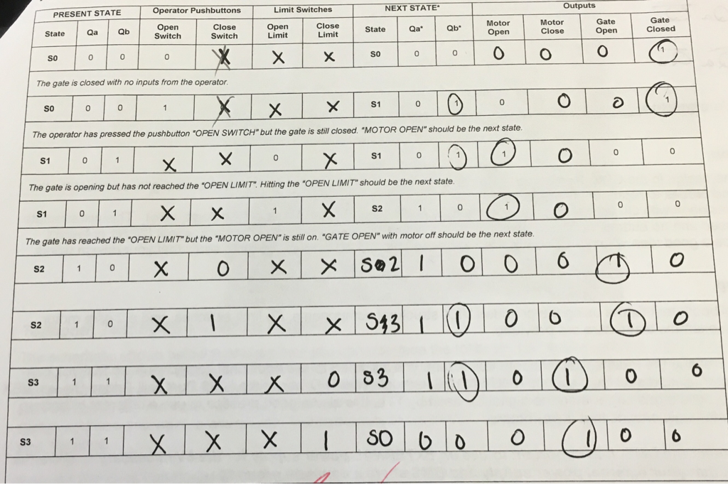
Transition Table
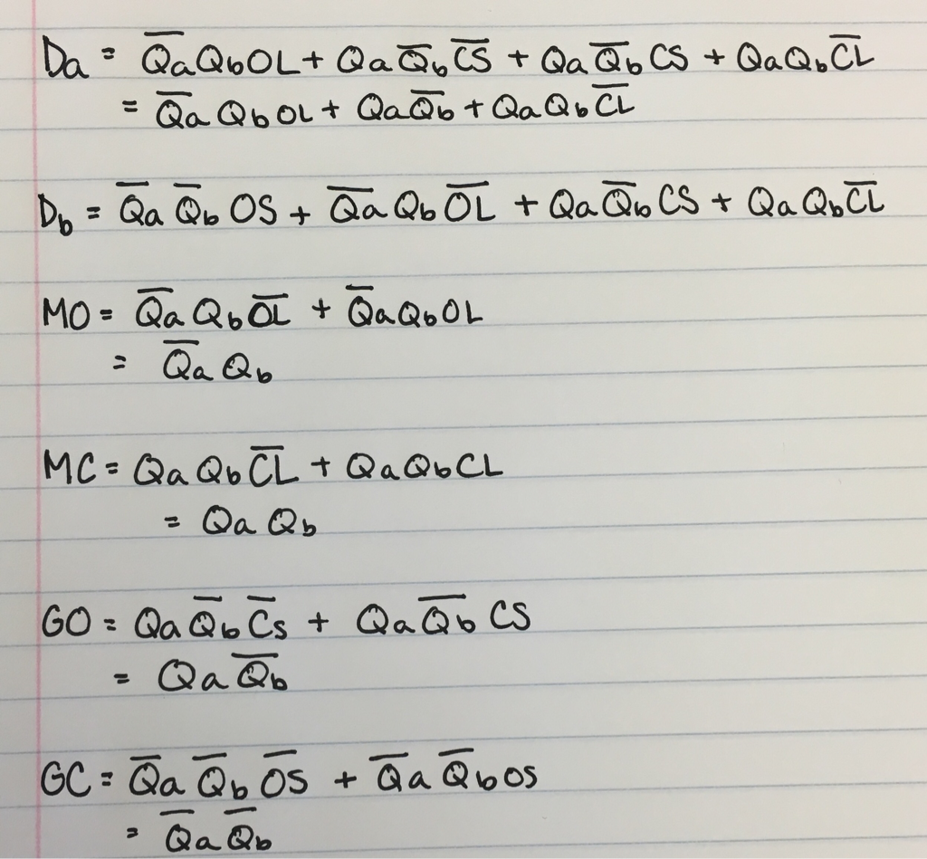
Boolean Algebra & Simplified Logic Expressions
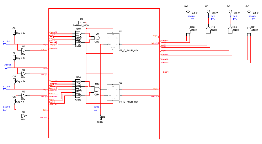
PLD MulitSim Circuit
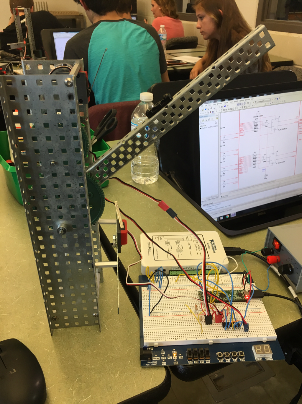
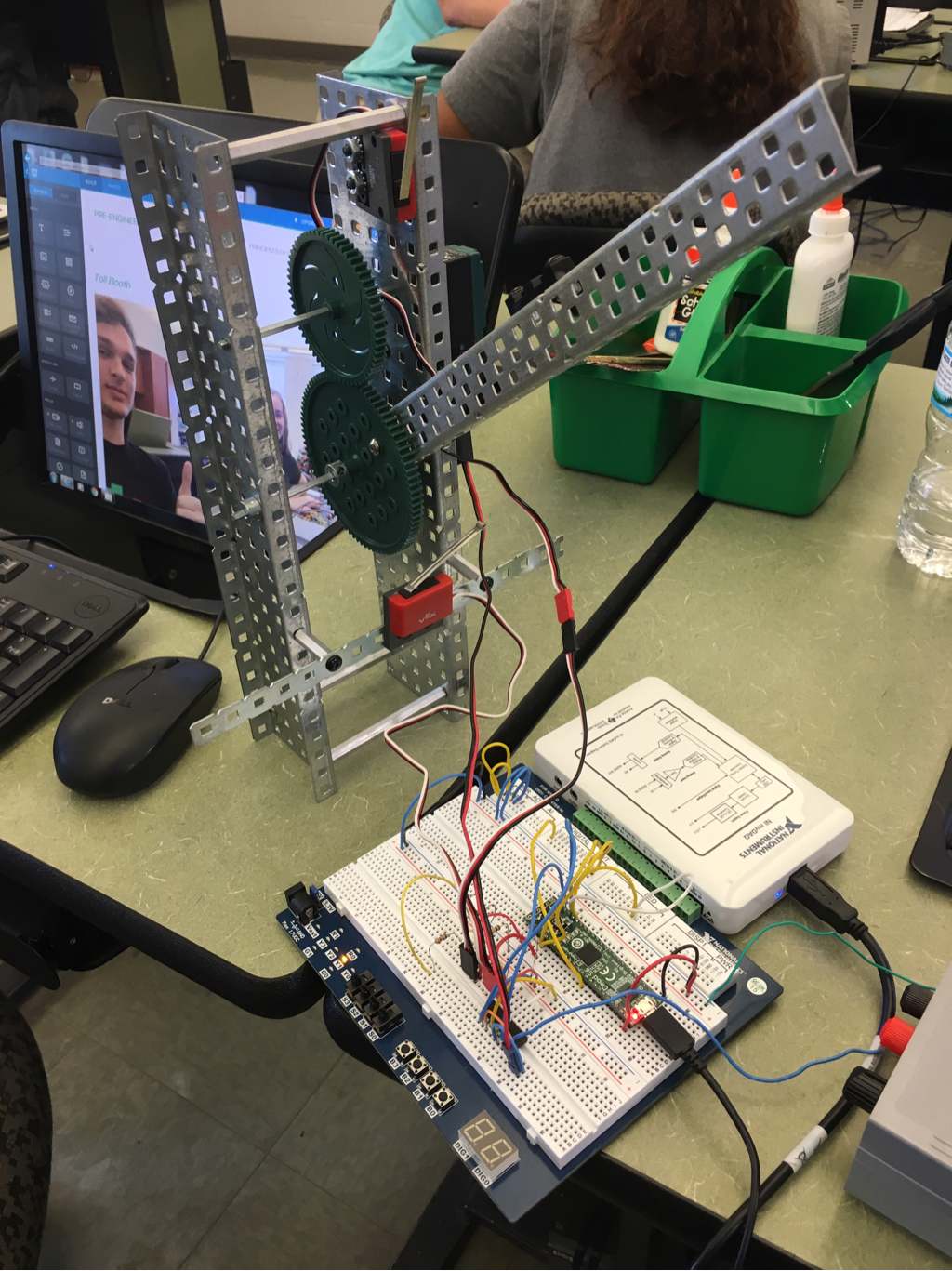
VEX Prototype
|
|
Conclusion
Dear Dr. Bergonia,
In this project my partner and I had to design a state machine that is a toll booth. The toll booth's arm had to move from the open position to the closed position just by flipping a switch. This project taught me to take advantage of my strengths, and my partners strengths. By relying on each other's strengths, my partner and I were able to complete the project with a lot less help from Ms. Zienty than we had needed in other projects. My own strengths were my understanding of how state machines work. I was the one who did a lot of the work on paper that relates to the process of the toll booth and getting the minterms that we needed to make the circuit. My partner, Gavin, was strong in being able to read the diagram that was given so that we could breadboard the circuit needed to make the toll booth work. Gavin and I are both pretty bad at making the Multisim circuits work so that part was a challenge. The first one that we built didn't work so we had to go back and check and recheck all of the inputs and outputs. We couldn't find the issue so we eventually decided to delete all of the inputs that we had and start over. The second time that we did it the circuit worked and we were able to download it to our toll booth so that it would work. Along with making the Multisim circuit together, we also built the structure together. When building it we used two limit switches and a motor that would raise the arm to the desired position. We ran into the problem that since the placement of the arm of the toll booth on the structure, an the direction that the limit switches face, the arm couldn't hit the lower limit switch. Gavin and I decided to place a bar across the front of the toll booth that would hold the limit switch so that the arm could hit it. Although this project was similar to the others projects that we have done in a lot of ways, it was also very different. This project used flip flops like the other projects, so Gavin and I already knew how to wire the inputs and the outputs of them, making the project much easier. Also, we already knew how to make the combinations with the AND and OR gates so that was really easy. It was much different from the other projects that we have completed because the work that had to be completed prior to the circuit begin made was new, and related to state machines. It was very easy for me to see how the state graph works, and what information needed to be pulled from it to make the state table. Also, the state table was very easy to read to get minterms. If I had to do this project over again, I would focus on using the diagram, instead of the picture of the breadboard that was given. By looking at the picture the first time I tried to breadboard, I ended up confusing my self because none of the PIOs were the same. Using the diagram I was able to do it easier.
In this project my partner and I had to design a state machine that is a toll booth. The toll booth's arm had to move from the open position to the closed position just by flipping a switch. This project taught me to take advantage of my strengths, and my partners strengths. By relying on each other's strengths, my partner and I were able to complete the project with a lot less help from Ms. Zienty than we had needed in other projects. My own strengths were my understanding of how state machines work. I was the one who did a lot of the work on paper that relates to the process of the toll booth and getting the minterms that we needed to make the circuit. My partner, Gavin, was strong in being able to read the diagram that was given so that we could breadboard the circuit needed to make the toll booth work. Gavin and I are both pretty bad at making the Multisim circuits work so that part was a challenge. The first one that we built didn't work so we had to go back and check and recheck all of the inputs and outputs. We couldn't find the issue so we eventually decided to delete all of the inputs that we had and start over. The second time that we did it the circuit worked and we were able to download it to our toll booth so that it would work. Along with making the Multisim circuit together, we also built the structure together. When building it we used two limit switches and a motor that would raise the arm to the desired position. We ran into the problem that since the placement of the arm of the toll booth on the structure, an the direction that the limit switches face, the arm couldn't hit the lower limit switch. Gavin and I decided to place a bar across the front of the toll booth that would hold the limit switch so that the arm could hit it. Although this project was similar to the others projects that we have done in a lot of ways, it was also very different. This project used flip flops like the other projects, so Gavin and I already knew how to wire the inputs and the outputs of them, making the project much easier. Also, we already knew how to make the combinations with the AND and OR gates so that was really easy. It was much different from the other projects that we have completed because the work that had to be completed prior to the circuit begin made was new, and related to state machines. It was very easy for me to see how the state graph works, and what information needed to be pulled from it to make the state table. Also, the state table was very easy to read to get minterms. If I had to do this project over again, I would focus on using the diagram, instead of the picture of the breadboard that was given. By looking at the picture the first time I tried to breadboard, I ended up confusing my self because none of the PIOs were the same. Using the diagram I was able to do it easier.
